
The term digital in electronics represents the data generation, processing or storing in the form of two states. The two states can be represented as HIGH or LOW, positive or non-positive, set or reset which is ultimately binary. The high is 1 and low is 0 and hence the digital technology is expressed as series of 0’s and 1’s. An example is 011010 in which each term represents an individual state. Thus, this latching process in hardware is done using certain components like latch or Flip-flop, Multiplexer, Demultiplexer, Encoders, Decoders and etc collectively called as Sequential logic circuits.
So, we are going to discuss about the Flip-flops also called as latches. The latches can also be understood as Bistable Multivibrator as two stable states. Generally, these latch circuits can be either active-high or active-low and they can be triggered by HIGH or LOW signals respectively.
The common types of flip-flops are,
Out of the above types only JK and D flip-flops are available in the integrated IC form and also used widely in most of the applications. Here in this article we will discuss about D type Flip Flop.
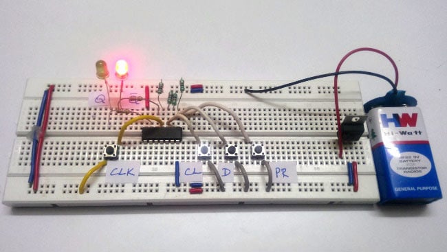
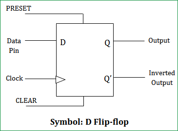
D Flip-flops are used as a part of memory storage elements and data processors as well. D flip-flop can be built using NAND gate or with NOR gate. Due to its versatility they are available as IC packages. The major applications of D flip-flop are to introduce delay in timing circuit, as a buffer, sampling data at specific intervals. D flip-flop is simpler in terms of wiring connection compared to JK flip-flop. Here we are using NAND gates for demonstrating the D flip flop.
Whenever the clock signal is LOW, the input is never going to affect the output state. The clock has to be high for the inputs to get active. Thus, D flip-flop is a controlled Bi-stable latch where the clock signal is the control signal. Again, this gets divided into positive edge triggered D flip flop and negative edge triggered D flip-flop. Thus, the output has two stable states based on the inputs which have been discussed below.

Truth table of D Flip-Flop:
Clock
INPUT
OUTPUT